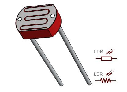
LDR INTERFACING WITH 8051
A Light Dependent Resistor (LDR) or a photo resistor is a passive electronic component, basically a resistor which has a resistance that varies depending of the light intensity.
Synopsis

A Light Dependent Resistor (LDR) or a photo resistor is a passive electronic component, basically a resistor which has a resistance that varies depending of the light intensity. A photo-resistor is made of a high resistance semiconductor that absorbs photons and based on the quantity and frequency of the absorbed photons the semiconductor material give bound electrons enough energy to jump into the conduction band. The resulting free electrons conduct electricity resulting in lowering resistance of the photo-resistor. The number of electrons is dependent of the photons frequency. LDR Connected with ADC0808 and then interface controller.

Description

LDR is used to provide the analog input. The output of the LDR is displayed on a 16x2 LCD. The output pins of ADC are connected to the GPIO port. The controller continuously monitors the output of the ADC. The output of the LDR varies with the intensity of light. The value ADC output varies from 0 to 255. The output of ADC is converted to decimal form and then displayed on the LCD. If the output of any of the LDR varies, the corresponding change is reflected on LCD screen.

LDR


Photo conductivity is an optical phenomenon in which the materials conductivity is increased. When light is absorbed by the material. When light falls i.e. when the photons fall on the device, the electrons in the valence band of the semiconductor material are excited to the conduction band. These photons in the incident light should have energy greater than the band gap of the semiconductor material to make the electrons jump from the valence band to the conduction band. Hence when light having enough energy strikes on the device, more and more electrons are excited to the conduction band which results in large number of charge carriers. The result of this process is more and more current starts flowing through the device when the circuit is closed and hence it is said that the resistance of the device has been decreased.

LDR’s are light dependent devices whose resistance is decreased when light falls on them and that is increased in the dark. When a light dependent resistor is kept in dark, its resistance is very high. This resistance is called as dark resistance. It can be as high as 1012Ω and if the device is allowed to absorb light its resistance will be decreased drastically. If a constant voltage is applied to it and intensity of light is increased the current starts increasing. Figure below shows resistance vs. illumination curve for a particular LDR.


Photocells or LDR’s are non-linear devices. There sensitivity varies with the wavelength of light incident on them. Some photocells might not at all response to a certain range of wavelengths. Based on the material used different cells have different spectral response curves.

When light is incident on a photocell it usually takes about 8 to 12 ms for the change in resistance to take place, while it takes one or more seconds for the resistance to rise back again to its initial value after removal of light. This phenomenon is called as resistance recovery rate. This property is used in audio compressors. LDR’s are less sensitive than photo diodes and phototransistor. (A photo diode and a photocell (LDR) are not the same, a photo-diode is a pn junction semiconductor device that converts light to electricity, whereas a photocell is a passive device, there is no pn junction in this nor it “converts” light to electricity).

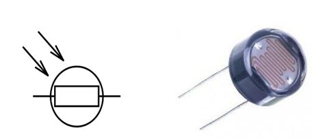
Types of Light Dependent Resistors

1. Intrinsic photo resistors (Un doped semiconductor): These are made of pure semiconductor materials such as silicon or germanium. Electrons get excited from valance band to conduction band when photons of enough energy fall on it and number charge carriers is increased.

2. Extrinsic photo resistors: These are semiconductor materials doped with impurities which are called as dopants. Theses dopants create new energy bands above the valence band which are filled with electrons. Hence this reduces the band gap and less energy is required in exciting them. Extrinsic photo resistors are generally used for long wavelengths.

The structure of a light dependent resistor consists of a light sensitive material which is deposited on an insulating substrate such as ceramic. The material is deposited in zigzag pattern in order to obtain the desired resistance and power rating. This zigzag area separates the metal deposited areas into two regions. Then the ohmic contacts are made on the either sides of the area.

The resistances of these contacts should be as less as possible to make sure that the resistance mainly changes due to the effect of light only. Materials normally used are cadmium sulphide, cadmium selenide, indium antimonide and cadmium sulphonide. The use of lead and cadmium is avoided as they are harmful to the environment.


Applications

1. Low cost and simple structure

2. Light sensors

3. Street lamps

4. Alarm clock

5. Burglar alarm circuits

6. Light intensity meters

Proteus design for LDR interfacing with 8051


Orcad design for LDR interfacing with 8051


/*  Name     : main.c
 *  Purpose  : Source code for LDR Interfacing with AT89C52.
 *  Author   : Gemicates
 *  Date     : 2017-06-15
 *  Website  : www.gemicates.org
 *  Revision : None
 */
 

 //Program to check the working of LDR using LCD on its output port.
#include <REGX52.H>

#define lcd P0						// LCD data pins
sbit rs = P1^5;  					// register select pin
sbit rw= P1^6;  					// read write pin
sbit e = P1^7;  					// enable pin

#define input P2  				        // Input port to read the values of ADC
#define output P0  				        // Output port, connected to LED's.

sbit wr= P1^1;  					// Write pin. It is used to start the conversion. 
sbit rd= P1^0;  					// Read pin. It is used to extract the data from internal register to the output pins of ADC.
sbit intr= P1^2;  				        // Interrupt pin. This is used to indicate the end of conversion. It goes low when conversion is complete.

unsigned char number,value,v1,v2,v3;

void delay(unsigned int msec )                          // The delay function provides delay in msec.
{
	int i,j ;
	for(i=0;i<msec;i++)
  for(j=0;j<1275; j++);
}

void lcddata(char t)			                // lcd data function
{
rs=1;
lcd=t;	
rw=0;
e=1;
delay(1);
e=0;
}

void cmd(unsigned char c)		                // lcd command function
{
lcd=c;
rs=0;
rw=0;
e=1;
delay(1);
e=0;
}

void com()   						// lcd initialization function
{
cmd(0x38);
delay(10);
cmd(0x0c);
delay(10);
cmd(0x01);
delay(10);
}

void string(char *d)		                        // lcd string print function
{
while(*d !=0)
{
	lcddata(*d++);
}
}

void BCD()						// BCD conversion function
{
	number=output;
	value=number;
	v1=value/100+0x30;
	v2=value%100/10+0x30;
	v3=value%10+0x30;
	string("value :");
	cmd(0x88);
	lcddata(v1);
	lcddata(v2);
	lcddata(v3);
	
//	value=number*19.62;
//	v1=value/100+0x30;
//	v2=value%100/10+0x30;
//	v3=value%10+0x30;
//      cmd(0xc0);
//	
//	string("volts :");
//	cmd(0xc8);
//	lcddata(v1);
//	lcddata('.');
//	lcddata(v2);
//	lcddata(v3);
}


void adc()  					        // Function to read the values from ADC0804 and display on the LCD.
{
	rd=1;     
	wr=0;     
	delay(1);
	wr=1;
	while(intr==1);
	rd=0;
	output=input;
	BCD();
	delay(1);
	intr=1;
}


void main()
{
  input=0xff;  					        // Declare port 2 as input port.       
	while(1)
	{
		com();
    adc();
		delay(100);
  }
}

Error message here!

Show Error message here!


Forgot your password?

Error message here!

Send OTP

Error message here!

Show Error message here!


Lost your password? Please enter your email address. You will receive a password you Need.

Send Error message here!


Back to log-in

Close